PNP Transistor
Symbol

Information
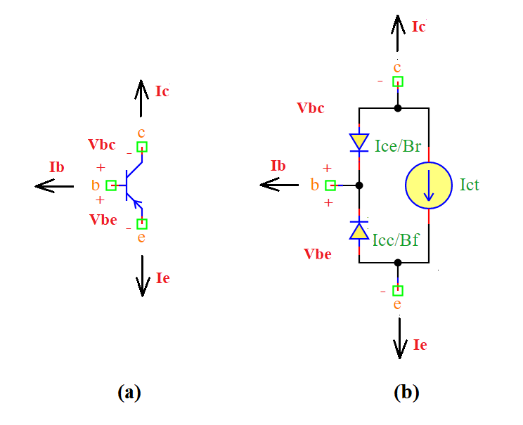
A PNP transistor is a three-terminal semiconductor device used for amplification and switching applications. In a PNP transistor, current flows from the emitter to the collector, controlled by the base current. It follows the Ebers-Moll model to define its behavior.
Ports
c: Collector terminal
b: Base terminal
e: Emitter terminal
Model
The PNP Transistor model implements a basic Bipolar Junction Transistor (BJT).
A PNP transistor allows current flow when the base is at a lower potential than the emitter.
Attributes:
Vbe (signal): Base-emitter voltage.
Vbc (signal): Base-collector voltage.
Vce (signal): Collector-emitter voltage.
Ic (signal): Collector current.
Ib (signal): Base current.
Ie (signal): Emitter current.
Nf (param): Forward current emission coefficient (default: 1.0).
Nr (param): Reverse current emission coefficient (default: 1.0).
Is (param): Transport saturation current (default: 1.0e-16 A).
area (param): Device area scaling factor (default: 1.0).
Br (param): Ideal maximum reverse beta (default: 1.0).
Bf (param): Ideal maximum forward beta (default: 100.0).
Vt (param): Thermal voltage (default: 0.025 V).
Var (param): Reverse Early voltage (default: 1e+3 V).
Vaf (param): Forward Early voltage (default: 1e+3 V).
gmin (param): Minimum conductance (default: 1e-12 1/Ohm).
Methods:
analog(): Defines the transistor behavior using the Ebers-Moll model:
from pyams.lib import model, signal, param, voltage, current, explim

class PNP(model):
    """
    Simple PNP Transistor model using the Ebers-Moll equations.
    """

    def __init__(self, c, b, e):
        # Signal declaration
        self.Vbe = signal('in', voltage, b, e)
        self.Vbc = signal('in', voltage, b, c)
        self.Vce = signal('in', voltage, c, e)
        self.Ic = signal('out', current, c)
        self.Ib = signal('out', current, b)
        self.Ie = signal('out', current, e)

        # Parameter declaration
        self.Nf = param(1.0, ' ', 'Forward current emission coefficient')
        self.Nr = param(1.0, ' ', 'Reverse current emission coefficient')
        self.Is = param(1.0e-16, 'A', 'Transport saturation current')
        self.area = param(1.0, ' ', 'Area')
        self.Br = param(1.0, ' ', 'Ideal maximum reverse beta')
        self.Bf = param(100.0, ' ', 'Ideal maximum forward beta')
        self.Vt = param(0.025, 'V', 'Voltage equivalent of temperature')
        self.Var = param(1e+3, 'V', 'Reverse Early voltage')
        self.Vaf = param(1e+3, 'V', 'Forward Early voltage')
        self.gmin = param(1e-12, '1/Ohm', 'Minimum conductance')

    def analog(self):
        """Defines the transistor’s current-voltage relationships using the Ebers-Moll model."""
        Vt = self.Vt
        Icc = self.Is * (explim(-self.Vbe / (self.Nf * Vt)) - 1)
        Ice = self.Is * (explim(-self.Vbc / (self.Nr * Vt)) - 1)
        Ict = (Icc - Ice) * (1 - self.Vbc / self.Vaf - self.Vbe / self.Var)
        self.Ic += -Ict + Ice / self.Br + self.gmin * self.Vbc
        self.Ib += -Ice / self.Br - Icc / self.Bf
        self.Ie += Ict + Icc / self.Bf + self.gmin * self.Vbe
Command syntax
The syntax for defining a PNP transistor in a PyAMS simulation:
# Import the model
from pyams.models import PNP

# Tname: is the name of the transistor instance
# c, b, e: The connection points in the circuit
Tname = PNP(c, b, e)