LC Oscillator Simulation
Overview
The circuit consists of an inductor (L1) and a capacitor (C1) forming an LC oscillator. The capacitor stores energy in an electrostatic field, producing a potential voltage across its plates, while the inductor stores energy in an electromagnetic field.
Initially, the capacitor is charged to Ic = 5V. When the capacitor discharges through the inductor, energy oscillates between the capacitor and the inductor, generating a sinusoidal waveform.
Oscillation Frequency
The resonant frequency of the LC circuit is given by:
For this simulation:
Resonant Frequency: fr = 0.5 Hz
Time Period: T = 2 s
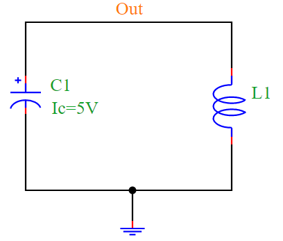
Circuit Diagram
The LC oscillator circuit is illustrated in the following diagram:
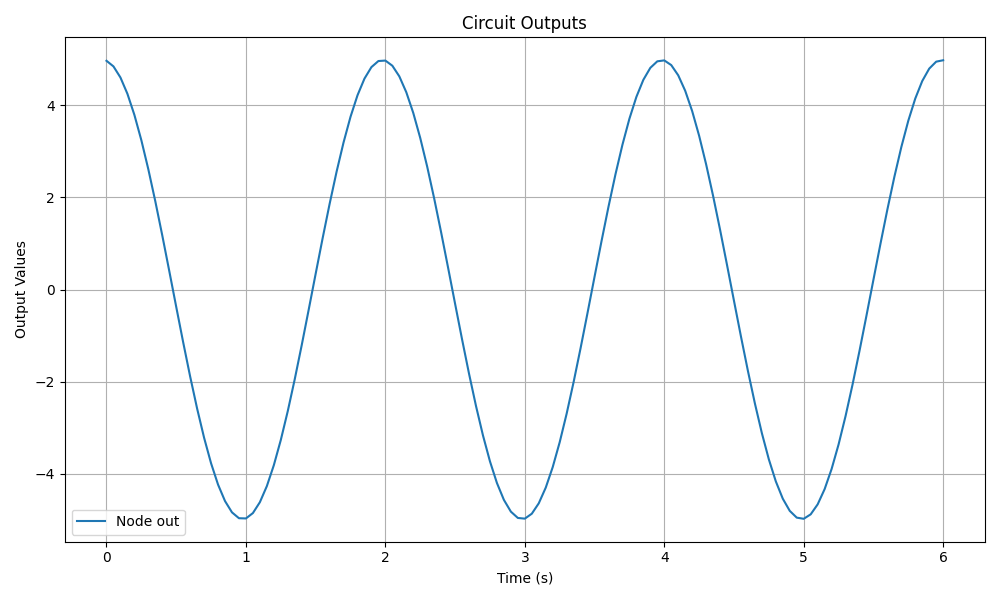
Simulation Output
The simulation generates the following sinusoidal waveform:
Conclusion
The LC oscillator generates an AC waveform due to the continuous exchange of energy between the inductor and capacitor. The PyAMS simulation verifies this behavior by producing a sinusoidal voltage output over time.