RC Circuit Simulation
Overview
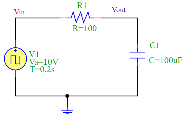
The circuit consists of a resistor (R1) and a capacitor (C1) forming an RC circuit. The circuit is driven by a square wave voltage source (V1).
When the input voltage Vin switches from low to high, the capacitor C1 begins charging through the resistor R1.
When Vin switches from high to low, the capacitor discharges.
This creates a characteristic exponential charging and discharging behavior.
Time Constant
The time constant (τ) of an RC circuit is given by:
For this simulation:
Resistance: R = 100 Omega
Capacitance: C = 100 mu F
Time Constant: τ = 100 × 100 × 10^{-6} = 0.01 s
Circuit Diagram
The following diagram illustrates the RC circuit:
Simulation Output
The output voltage Vout follows an exponential response due to the capacitor’s charging and discharging behavior. The simulation produces the following waveform:
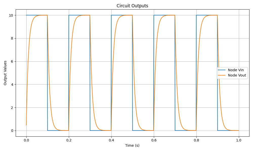
Conclusion
The RC circuit acts as a low-pass filter, smoothing the square wave input into a more gradual exponential waveform. The simulation confirms this behavior by displaying the expected charging and discharging curves.