Voltage Divider Simulation
Overview
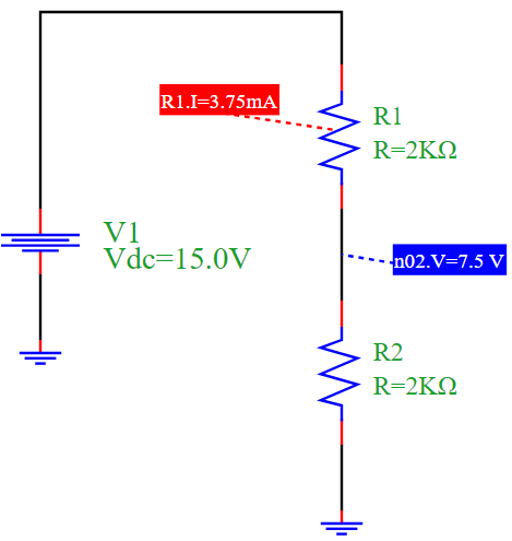
This example demonstrates a basic voltage divider circuit using PyAMS, which is commonly used to scale down voltages. The circuit consists of:
A DC voltage source V1
Two resistors R1 and R2 in series
The output voltage is measured across R2
The circuit divides the voltage proportionally based on the resistor values.
Circuit Diagram
Explanation
According to the voltage divider rule, the voltage across R2 is given by:
\[V_{out} = V_{in} \cdot \frac{R2}{R1 + R2}\]
Given: - \(V_{in} = 15V\) - \(R1 = R2 = 2k\Omega\)
Then:
\[V_{out} = 15 \cdot \frac{2000}{2000 + 2000} = 7.5V\]
The current through the series resistors is:
\[I = \frac{V_{in}}{R1 + R2} = \frac{15}{4000} = 3.75mA\]
Simulation Results
Output Voltage at node n2: 7.5 V
Output Current through R1: 3.75 mA