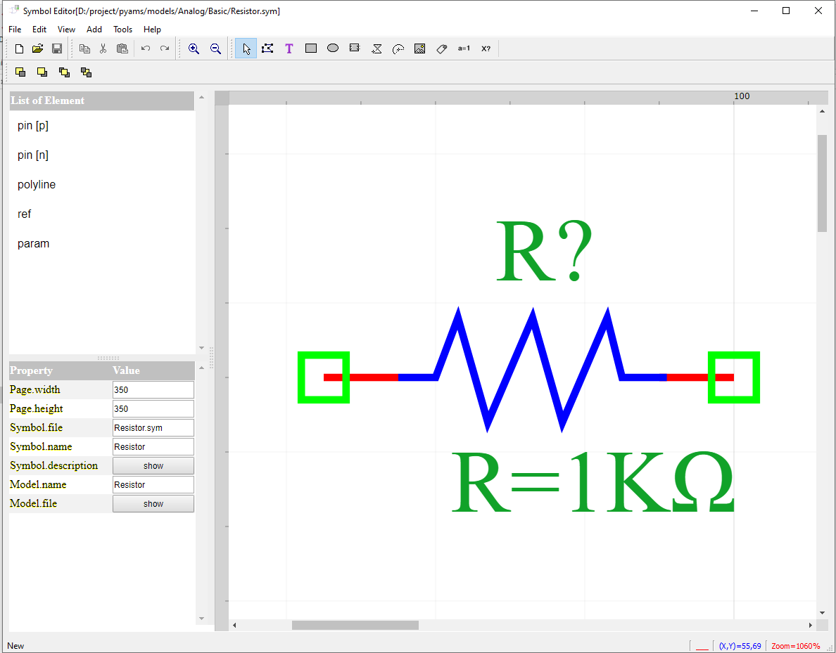
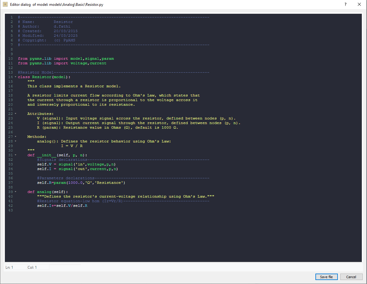
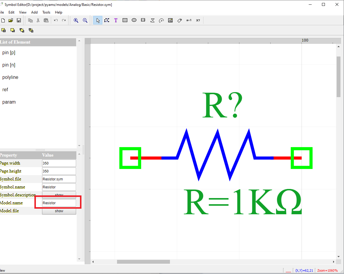
The analog elements in the circuit are designed by the symbol editor (Fig. 1) it presented PyAMS model (Fig. 2).
The graphical interface of the editor of symbols includes:
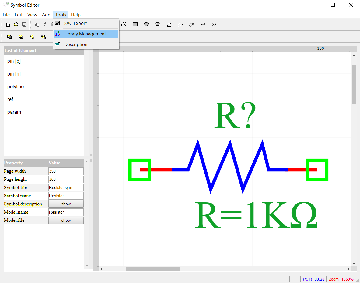
The creating of symbols in the editor is based on the following steps:
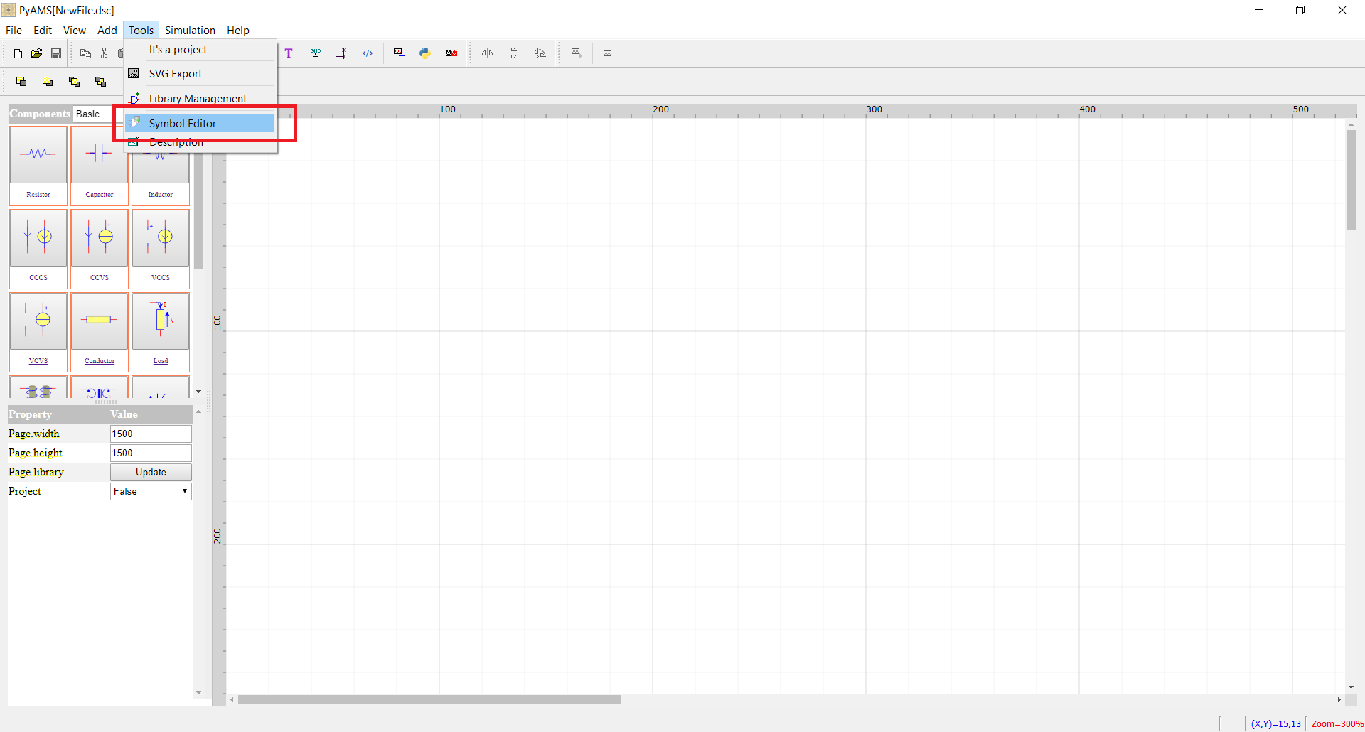
Step 1 Open editor of symbol from PyAMS
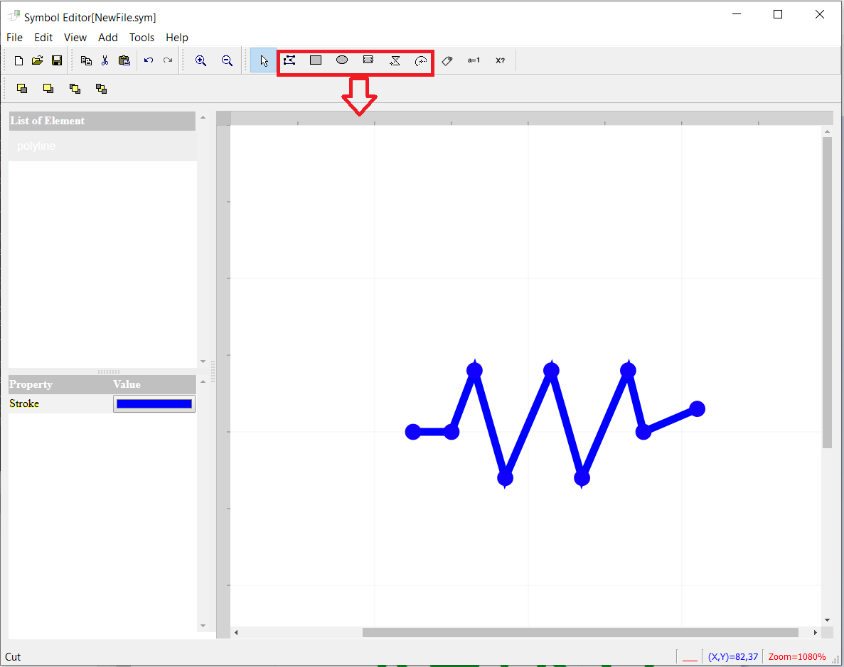
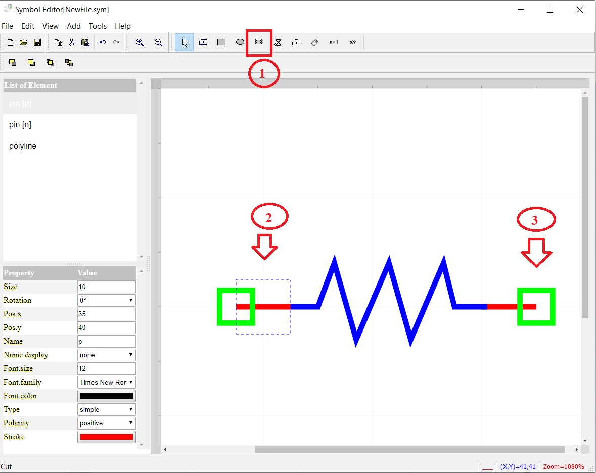
Step 2 Draw the electrical elements by lines, rectangles, ellipse ….etc.
Step 3 Add ports or pins.
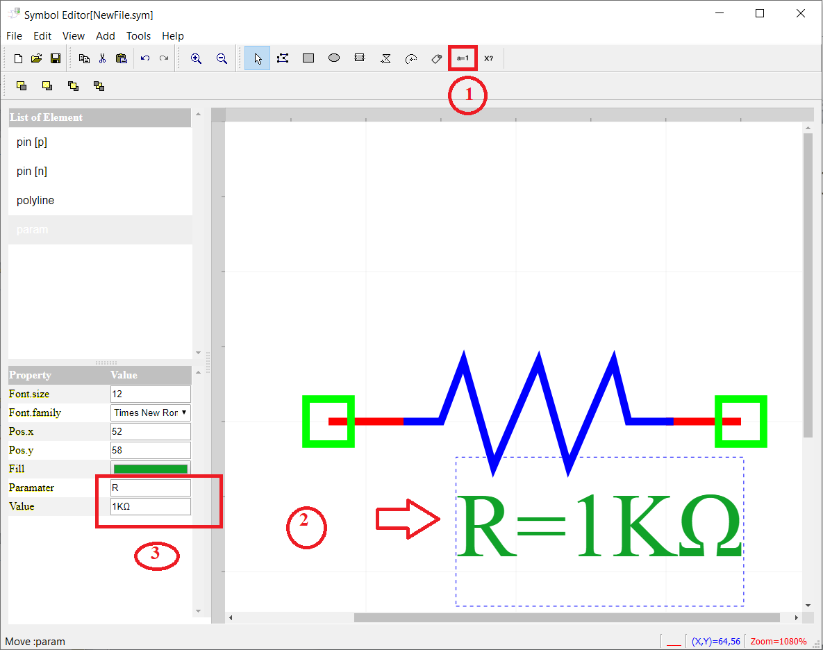
Step 4 Add parameters and edit name and value .
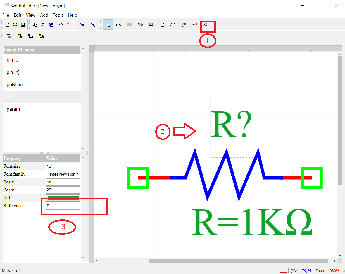
Step 5 Add reference and edit name.
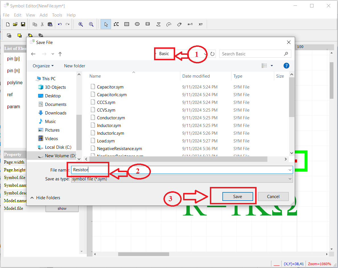
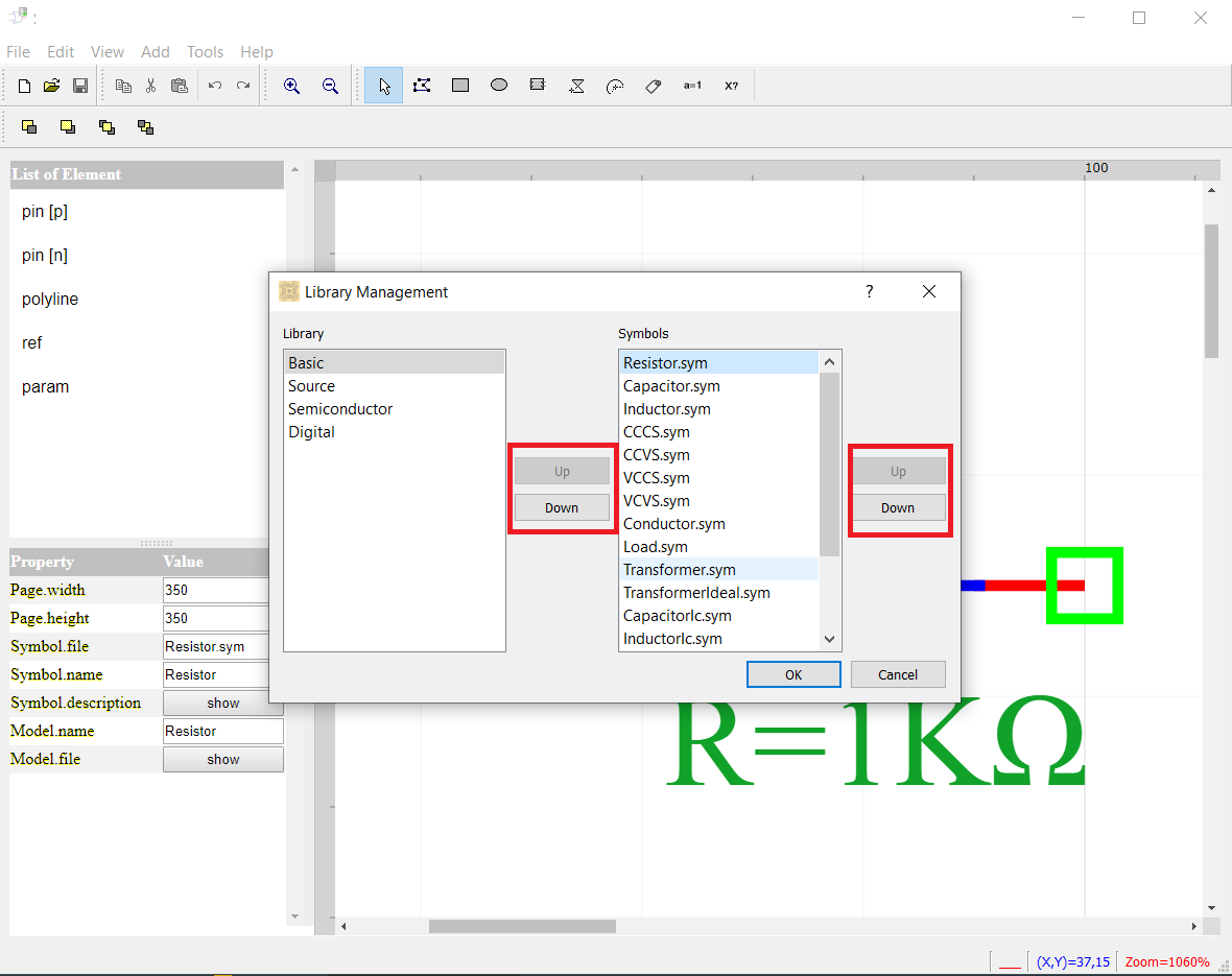
Step 6 Save the new symbol to one of the folders in the models.
Step 7 Add name of model and edit name.
Note
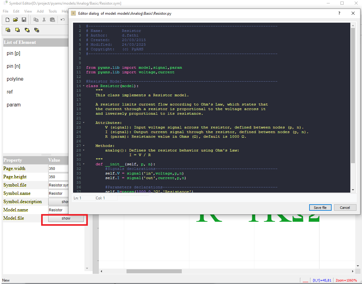
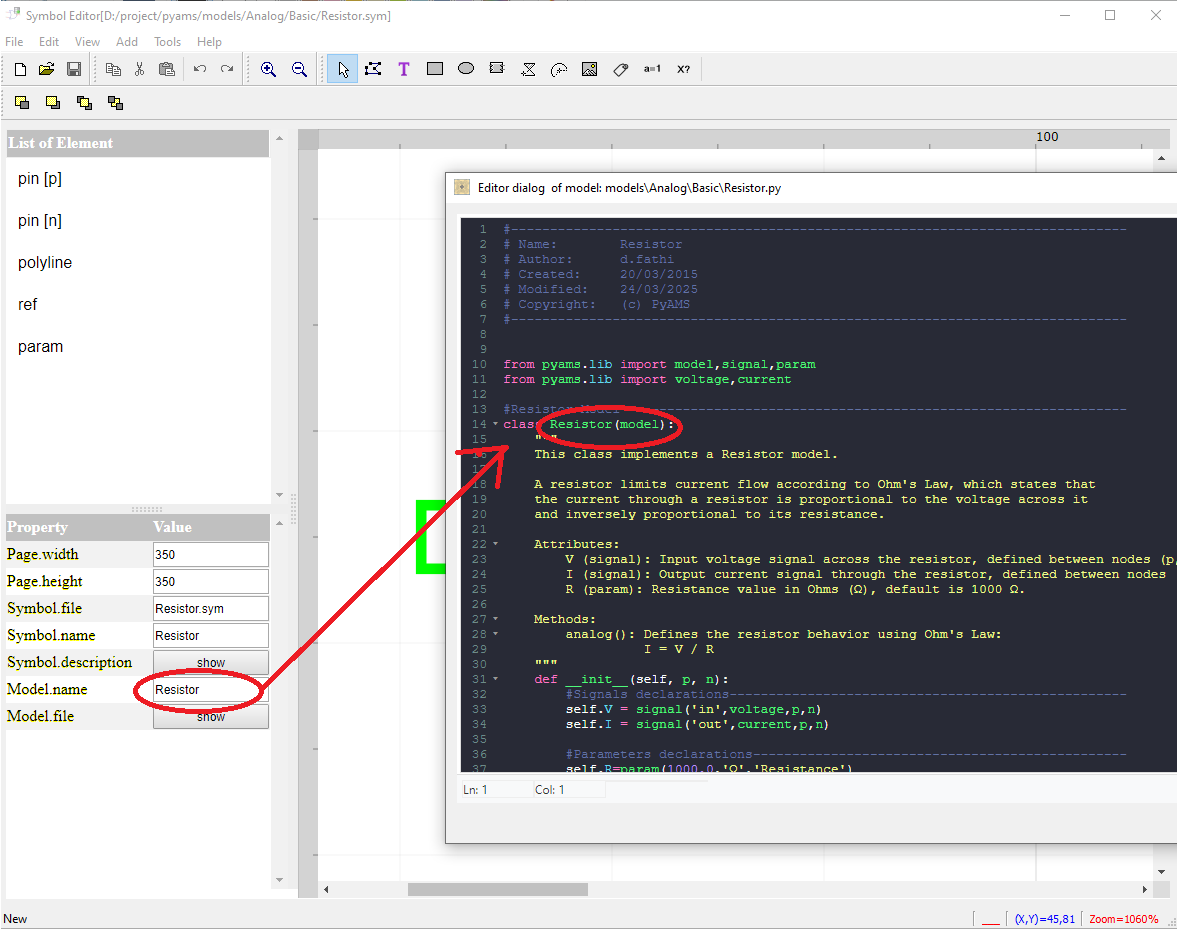
The name of the model must be added in the line of Model.name, and the code should be written using the editor by clicking the button for the Model.file and saving it in the directory of models.
Step 8 Create a PyAMS model for resistance..
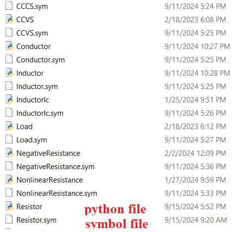
you can attach symbol with PyAMS model by placed or saved in the same directory with the same name of model with extension *.py
The modeling of analog elements in PyAMS is based on writing their description using the Python language respecting the following structure:
Declaration of the library;
Creation of the name of the model;
Adding parameters with an initial value;
Adding type of signals (current or voltage);
Adding sub-models if available;
Definition of relations between signals and parameters;
Note
The name of model must have the same name Model.name in the symbol editor.
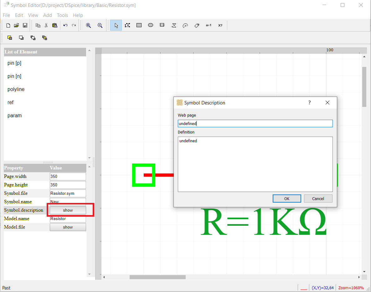
Step 8 You can add a description of symbol to help the designer (using the Help menu).